

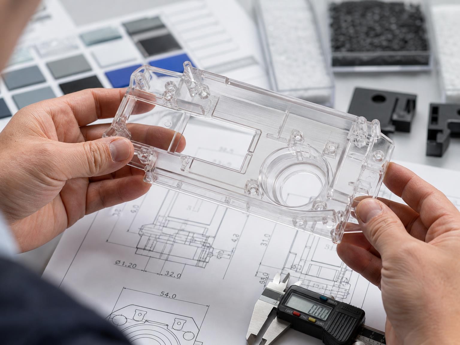
Injection molding can turn out thousands of nearly identical plastic parts with impressive consistency, but that repeatability is earned long before anyone cuts steel. Wall thickness, material selection, draft angles, and tolerance choices all interact in ways that determine whether a part molds cleanly or ends up needing costly rework. Most of these problems are far cheaper to catch on a screen than inside a mold. That’s why some design teams bring in a manufacturing partner early—consulting, for instance, an injection molding company in Austin or another qualified facility during a design-for-manufacturing review, just to get practical feedback before tooling begins. This isn’t an endorsement of any particular provider; it’s simply an example of how early technical input can cut down on downstream risk.
Start With the Part’s Function and Operating Environment
Before picking a resin or sketching any geometry, nail down what the part actually has to do. Will it bear structural load, absorb impact, resist chemicals, withstand UV exposure, or provide electrical insulation? Does it need a particular cosmetic finish, or does it have to meet a regulatory standard? Sorting out cosmetic, structural, dimensional, and regulatory requirements early on prevents competing priorities from colliding later in the process.
It’s also worth remembering that resin datasheet values are typically generated under controlled lab conditions, not real-world ones—so they shouldn’t be mistaken for guaranteed performance. Verifying material data against manufacturer technical documentation, and testing under conditions that actually resemble end use, goes a long way toward avoiding unpleasant surprises once tooling is built.
Choose a Material Based on Performance, Not Habit
Compare Common Thermoplastic Categories
Different thermoplastics come with different trade-offs. ABS tends to get picked for impact resistance and general-purpose housings. Polycarbonate brings toughness along with optical clarity options. Polypropylene stands out for chemical resistance and flexibility. Nylon offers strength and wear resistance, while acetal is known for low friction and dimensional stability. Amorphous and semi-crystalline plastics can also behave quite differently when it comes to shrinkage, stiffness, and chemical resistance. No single material is right for every job—selection should follow function, not familiarity.
| Material | Common Strength | General Consideration |
|---|---|---|
| ABS | Impact resistance | Moderate chemical resistance |
| Polycarbonate | Toughness, clarity | Sensitive to certain cleaners |
| Polypropylene | Chemical resistance, flexibility | Lower stiffness |
| Nylon | Strength, wear resistance | Can absorb moisture |
| Acetal | Low friction, stability | Limited UV resistance |
Think of these as general starting points rather than hard rules—actual behavior still depends on grade, additives, and part geometry.
Account for Additives and Reinforcements
Glass fiber, mineral fillers, flame retardants, colorants, and UV stabilizers can all shift how a resin flows, shrinks, and performs over time. Reinforced grades may also chew through tooling faster or introduce directional strength differences that aren’t always obvious up front. Documenting the exact grade—not just the base polymer family—helps keep results consistent, and checking manufacturer datasheets alongside relevant material standards supports better-informed decisions.
Apply Design-for-Manufacturing Principles
Maintain Practical Wall Thickness
Uneven wall thickness is one of the most common culprits behind sink marks, warping, and uneven cooling. Where uniform thickness just isn’t feasible, gradual transitions help ease stress concentrations. Acceptable thickness ranges vary by resin, part size, and flow length, so general guidelines need to be adjusted to fit the specific application. Ribs, gussets, and hollowed sections are often a smarter way to add strength than simply thickening the walls.
Add Draft to Support Ejection
Draft angles let a part release cleanly from the mold without scuffing or distorting. One to two degrees is a common starting point, though textured surfaces usually call for more. The right angle depends on texture depth, material, and tool design, so draft deserves attention during CAD development rather than being tacked on as an afterthought.
Review Ribs, Bosses, Holes, and Undercuts
Thick ribs and bosses can create sink marks or localized cooling problems if they’re out of proportion to the surrounding walls. Core pins, generous internal radii, and thoughtful parting-line placement all shape tool complexity and final part quality. Undercuts generally call for slides or lifters, which add both cost and complexity.
Illustrative scenario: In one hypothetical case, a boss designed at nearly twice the surrounding wall thickness produced a visible sink mark on the opposite cosmetic surface. Reducing the boss wall thickness and adding a small radius at its base resolved the defect without changing the part’s function—a reminder that a small geometry adjustment can simplify tooling and improve appearance.
Set Tolerances According to Function
Tolerances describe the allowable variation around a specified dimension. Shrinkage, cooling rate, resin type, geometry, and even measurement method can all nudge final dimensions one way or another. Tight tolerances should be reserved for features that affect fit, motion, sealing, alignment, safety, or interchangeability—not applied blanket-style across every dimension. For assemblies with multiple molded parts, a tolerance-stack analysis is usually worth the effort. Production tolerances should ultimately be confirmed with the manufacturer and validated through first-article inspection or capability studies.
Key takeaway: The tightest tolerance isn’t automatically the best one. It should be justified by the part’s function and be something that can actually be held consistently in production—not chosen by default.
Plan Gates, Runners, Parting Lines, and Surface Appearance
Gate location affects how material fills the cavity, where weld lines show up, and how visible surfaces ultimately look. Parting-line placement influences flash risk, ejection, and tooling complexity. Cosmetic surfaces should be identified before mold design even begins, and flow simulation tends to pay off for parts with long flow paths, thin walls, multiple gates, or high cosmetic expectations. Because these decisions are interconnected, changing a gate location or material can ripple outward, shifting cooling behavior and dimensional outcomes elsewhere in the part.
Build Quality Into the Production Plan
Quality planning goes well beyond visual checks. It should cover dimensional inspection, material verification, functional testing, color consistency, and clear limits for flash or sink marks. Defining acceptance criteria before production starts—and documenting the approved material grade, mold revision, critical dimensions, and rework limits—gives everyone a consistent reference point. A first-article review helps confirm that the molded part matches design intent before full production begins, ideally measured against applicable industry standards or customer specifications rather than informal judgment calls.
Reduce Waste Without Sacrificing Performance
More uniform walls, fewer unnecessary features, efficient runner design, and well-controlled processes can all cut down on scrap and rework. Regrind may be appropriate in some applications, but it’s not a universal solution—performance, recyclability, and contamination risk all factor into that call. Environmental claims should be backed by documented material data, not assumptions.
A Practical Pre-Tooling Design Review Checklist
- Functional requirements and service conditions defined
- Resin grade selected and documented
- Wall thickness reviewed
- Draft angles added
- Ribs and bosses checked for sink risk
- Undercuts and parting lines evaluated
- Gates and cosmetic surfaces discussed
- Critical dimensions identified
- Tolerance stack analyzed
- Inspection and acceptance criteria established
- Prototype or design validation completed
- Manufacturing feedback obtained before tooling approval
Better Parts Begin With Better Decisions
Successful injection-molded parts come from coordinated decisions across function, material, geometry, tolerances, tooling, and quality control. Reviewing a design before mold construction starts—rather than after problems surface—tends to reduce rework and improve consistency. Documenting assumptions, verifying technical data, and consulting qualified manufacturing professionals when requirements get complex all contribute to a smoother path to production. Before committing to tooling, run the part against a structured checklist, confirm which dimensions are truly critical, and validate the design under conditions that reflect how it will actually be used.
Exact design limits vary by resin, geometry, tooling, and equipment; the guidance above represents general starting points rather than fixed rules.
Editor’s Note: The opinions expressed here by the authors are their own, not those of impakter.com — Cover Photo Credit: Texas Injection Molding.