

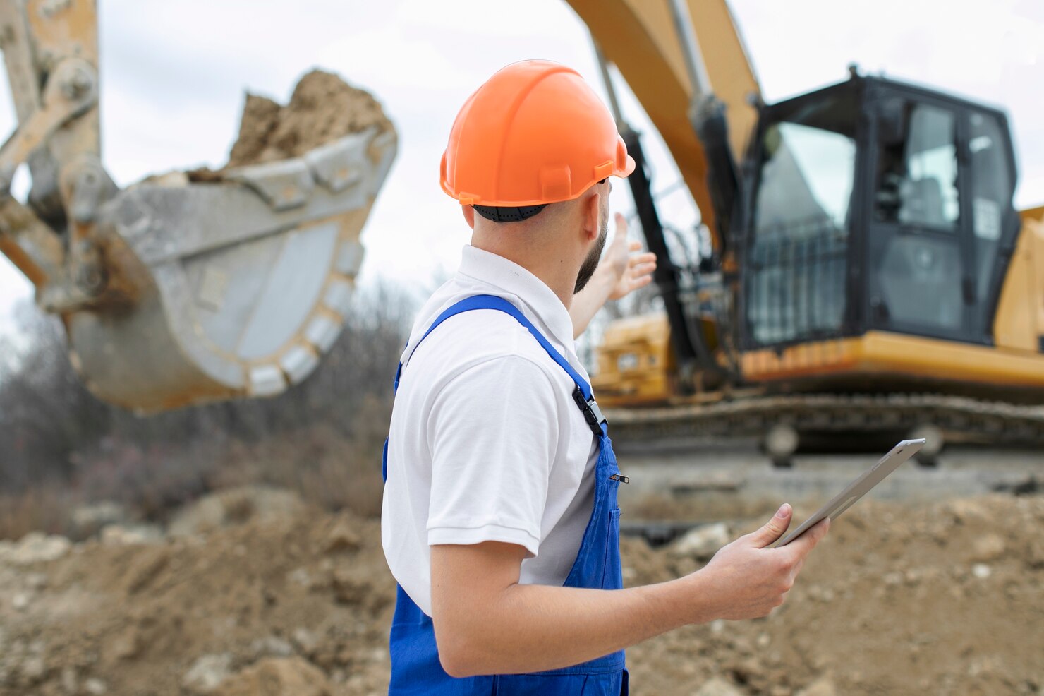
A mark on asphalt or a painted line across grass indicates that an underground utility exists nearby. It does not reveal its exact depth, its exact curvature, or whether an undocumented gas lateral crosses beneath it.
Every excavation professional understands the tension of digging inside the tolerance zone. Even when a site has undergone a thorough utility locate through an 811 call or private designating service, strikes remain a frequent and expensive jobsite hazard. Paint markings and pin flags represent historical records and surface-level estimations, not a live view of what lies six inches in front of an excavator bucket.
7 Core Technologies for Safe Excavation Around Buried Infrastructure
1. RodRadar
RodRadar introduces a significant operational evolution to the excavation process through its Live Dig RadarⓇ (LDR) technology. Rather than relying solely on pre-excavation surface surveys or stopping machine work entirely for slow manual digging, the platform integrates ground-penetrating radar directly into an excavator digging bucket.
This structural integration gives the excavator operator real-time subsurface visibility as earthmoving occurs. As the bucket engages the ground, the integrated radar module scans the earth immediately in front of and beneath the cutting teeth. Algorithms analyze the returned radar reflections to identify buried assets, including electrical lines, communications conduits, gas pipes, water mains, and sewer lines, and display actionable alerts directly on an in-cab monitor before the bucket makes physical contact.
A distinct advantage of LDR is its ability to identify both conductive and non-conductive utilities. Traditional electromagnetic wand locators require a metallic conductor or an active tracer wire to identify a pipe. RodRadar’s radar technology detects utilities of all types by measuring the dielectric contrast between the utility structure and the surrounding soil matrix.
Key features include:
- Ground-penetrating radar built directly into the excavator digging bucket
- Real-time detection of subsurface targets during active excavation passes
- In-cab operator interface displaying immediate proximity and depth alerts
- High sensitivity to both metallic and non-metallic utilities, including plastic and clay
- Continuous verification across varying soil types and congested utility corridors
- Direct integration onto standard hydraulic excavators without complex external cabling
2. Vacuum and Hydro Excavation Systems
Vacuum and hydro excavation, frequently grouped under the umbrella of soft digging or non-destructive excavation, represent the benchmark standard for visually verifying utility depth inside the tolerance zone. The technology replaces steel buckets with high-velocity kinetic energy to displace soil without puncturing, bending, or scraping buried infrastructure.
Hydro excavation systems direct pressurized water (typically between 1,500 and 3,000 PSI) through a handheld wand to break down compacted clay, frozen ground, and dense aggregate into a slurry. Concurrently, a powerful positive-displacement vacuum blower pulls the liquefied spoil through a large-diameter suction hose and deposits it into an integrated debris holding tank on a specialized truck chassis.
Key features include:
- Complete elimination of metal-to-pipe contact during soil displacement
- Non-destructive exposure of fragile telecommunications, fiber optics, and coated gas lines
- High-efficiency excavation through compacted soils, gravel, and frost layers
- Simultaneous soil fracture and debris extraction keeping the excavation pit clean
- Precise visual confirmation of pipe condition, joint locations, and crossing utilities
- Available in truck-mounted, trailer-mounted, and compact utility configurations
3. Electromagnetic (EM) Locators and Signal Transmitters
Electromagnetic locators form the foundation of day-to-day utility detection and damage prevention on civil jobsites. These two-part systems consist of an electromagnetic transmitter (signal generator) and an ergonomic handheld receiver used to trace the path and depth of buried metallic utilities.
The transmitter applies an alternating current signal of a specific frequency onto a targeted conductor. This can be accomplished through direct connection via conductive leads, signal induction via a specialized electromagnetic clamp wrapped around a pipe, or passive induction broadcasted from the surface. As the current travels along the metallic utility, such as a ductile iron water main, copper service line, or steel gas conduit, it radiates an electromagnetic field.
Key features include:
- High accuracy for tracing conductive metallic pipes, cables, and tracer wires
- Multi-frequency selection to overcome signal bleeding and soil interference
- Direct, induction, and passive locating modes for flexible field operation
- Continuous digital depth measurement and signal current direction verification
- Sonde and push-rod compatibility for mapping empty non-metallic conduits
- Rugged, weather-resistant handheld designs built for daily jobsite use
4. Surface Ground Penetrating Radar (GPR) Systems
Surface-towed and cart-mounted Ground Penetrating Radar (GPR) systems provide non-destructive, two-dimensional and three-dimensional geophysical imaging of the shallow subsurface prior to groundbreaking. Unlike electromagnetic locators, GPR does not require a conductive metal path or an active electrical signal.
A standard GPR cart emits high-frequency electromagnetic pulses (typically between 200 MHz and 900 MHz) into the ground through a surface antenna. As these radio waves travel through the soil, they encounter changes in the electrical properties of the earth, known as the dielectric permittivity boundary. When the radar wave strikes a material with a different dielectric constant, such as moving from dry sand to a solid PVC pipe or a metallic conduit, a portion of the wave reflects back to the surface receiving antenna.
Key features include:
- Reliable detection of both metallic and non-metallic buried structures
- Real-time generation of subsurface cross-sections and 2D/3D depth slices
- Dual-frequency and multi-channel antenna options for shallow and deep targets
- Integrated GPS and spatial encoders for georeferencing subsurface features
- Non-invasive surface deployment suitable for asphalt, concrete, and soil
- Accurate identification of historical foundations, voids, and undocumented utilities
5. 3D Machine Control and GNSS Utility Avoidance Systems
Three-dimensional machine control platforms bring digital engineering models directly into the heavy equipment cab, connecting GPS/GNSS positioning with automated hydraulic intervention. Traditionally used for bulk earthmoving and precision grade finishing, modern machine guidance systems increasingly incorporate subsurface utility mapping to prevent strikes.
The process begins by converting utility locates, SUE survey data, and design models into a georeferenced 3D digital terrain and utility model. This model is loaded onto the excavator’s primary control computer. Real-time Kinematic (RTK) GNSS antennas mounted on the machine’s counterweight or cab roof provide real-time spatial positioning, while angle sensors on the boom, stick, and bucket determine the exact coordinates of the bucket teeth in real time.
When the machine approaches a known utility corridor, the guidance software displays a live 3D visual of the bucket’s position relative to the buried infrastructure. Advanced systems can enforce virtual geofences, known as keep-out zones.
If an operator attempts to swing the boom or lower the stick into a predefined safety buffer around a high-pressure line, the machine control system triggers audible and visual alarms. Semi-autonomous configurations can automatically override the pilot hydraulics, halting the downward motion of the bucket before it penetrates the utility safety envelope.
Key features include:
- Centimeter-accurate RTK GNSS tracking of excavator bucket location
- Live 3D visualization of subsurface utilities directly on the in-cab display
- Configurable virtual geofences and keep-out corridors around high-risk lines
- Semi-autonomous hydraulic overrides that stop the bucket at the utility boundary
- Integration of design files, SUE survey records, and municipal GIS databases
- Continuous logging of excavation progress against digital site engineering plans
6. Pneumatic Air Excavation Systems (Air Lances)
Pneumatic air excavation technology utilizes high-pressure compressed air directed through specialized lances to break up soil without relying on water or steel edges. Commonly referred to as air spading, this technology is designed for selective soil removal around sensitive utilities where hydro excavation or grading presents operational challenges.
The equipment consists of a heavy-duty portable air compressor connected to a fiberglass or non-conductive composite lance terminating in an engineered supersonic nozzle. The nozzle accelerates the air stream to speeds exceeding Mach 1.5. When this high-velocity air hits compacted soil, it penetrates into the microscopic pores of the earth, expanding rapidly and fracturing the soil into small particles.
Key features include:
- Supersonic air nozzles engineered to fracture soil while protecting solid conduits
- Non-conductive, dielectric lance shafts protecting operators from electrical shock
- Fully dry excavation process allowing immediate on-site soil backfill
- Safe for clearing soil around delicate fiber bundles and aged pipe joints
- Avoids the weight, disposal, and water-sourcing constraints of hydro excavation
- Highly maneuverable in restricted residential easements and tree root zones
7. Acoustic and Inertial Gyroscopic Pipe Locators
Acoustic and inertial locators address one of the most persistent challenges in subsurface damage prevention: locating non-metallic, non-conductive utilities that have no tracer wire and are buried in soils that degrade ground-penetrating radar signals.
Acoustic locators operate on the principle of mechanical sound wave propagation. A transmitter or mechanical pulser is connected to an accessible point on a pipeline network, such as a fire hydrant, valve stem, or residential meter box. The transmitter introduces a distinct, controlled sound wave into the fluid or gas column inside the pipe. This acoustic signal travels down the pipe, vibrating the conduit walls and radiating a sound signature upward through the ground.
A field technician uses a specialized ground microphone and acoustic listening receiver to track the sound profile on the surface, locating the pipe path even through deep, dense clay that blocks radar waves. This technique is particularly effective for locating plastic (PVC/PE) water mains and private sewer services.
Key features include:
- Maps plastic, concrete, clay, and composite pipes without electrical conductors
- Unaffected by high-salinity or dense clay soils that limit GPR performance
- Non-invasive acoustic transmitters connect directly to standard valves and meters
- Autonomous gyroscopic probes record three-dimensional internal pipeline geometry
- Generates precise vector data for updating inaccurate municipal as-built drawings
- Ideal for deep gravity sewers, water distribution systems, and industrial conduits
Technical Comparison of Safe Excavation Technologies
Selecting the right technology depends on soil conditions, utility materials, operational velocity, and the phase of excavation. The table below outlines how these seven technologies compare across key operating parameters.
| Technology | Target Utility Types | Operational Phase | Detection Depth Limit | Primary Operational Advantage |
| RodRadar | Metallic & non-metallic (PVC, clay, fiber) | In-Dig Detection (before & during each bucket pass) | Scans beneath the bucket as it moves; soil-dependent | In-cab real-time alert directly from the bucket during active digging |
| Vacuum & Hydro Excavation | All buried utilities & structures | Pre-Dig Verification (Tolerance Zone) | Suction hose limit (up to 15+ ft) | Completely non-destructive physical daylighting and visual verification |
| Electromagnetic Locators | Metallic pipes, cables, and active tracer wires | Pre-Excavation Marking | Up to 15–20 ft (signal dependent) | Rapid tracing and depth estimation of conductive utilities |
| Surface GPR Systems | Metallic, non-metallic, voids, and vaults | Pre-Excavation Site Survey | 2–10+ ft (highly dependent on soil clay content) | Generates cross-sectional and 3D subsurface maps without hookups |
| 3D Machine Control Systems | Modeled utilities in digital site plans | Active Grading & Bulk Digging | Software buffer (unlimited depth) | Prevents bucket entry into digital keep-out corridors via machine guidance |
| Pneumatic Air Excavation | All utilities (cables, coated gas, roots) | Precise Daylighting & Hand Clearing | Practical hand-tool depth (3–6 ft) | Non-destructive dry excavation; immediate soil reuse for backfill |
| Acoustic & Gyroscopic Locators | Plastic water lines, concrete pipes, sewers | Pre-Excavation Mapping & Verification | Acoustic: 6–10 ft; Gyro: internal conduit mapping | Maps non-metallic pipes in difficult clay soils where GPR waves attenuate |
Best Practices for Digging Near Buried Infrastructure
Deploying advanced technology does not replace disciplined operational practices. To minimize strike risk when excavating near buried facilities, project managers and field crews should follow a layered damage prevention workflow:
- Review SUE Records Beyond 811 Marks: Obtain original utility records and engineering drawings to identify abandoned lines, private laterals, and industrial connections that municipal markout crews may not locate.
- Maintain Clear Tolerance Zone Boundaries: Clearly stake out the tolerance zone (typically 18 to 24 inches from the outer edge of the marked utility) and brief all operators that full-speed mechanical excavation must transition to verified detection protocols within this boundary.
- Verify with Non-Destructive Daylighting: Use vacuum excavation or pneumatic air lances to expose and visually confirm the utility’s depth, angle, and crossing lines before performing cross-trenching or bulk clearing.
- Deploy Real-Time In-Trench Verification: Utilize excavator-mounted detection systems like bucket-integrated radar when working inside corridors with known infrastructure, giving operators a continuous subsurface scan ahead of every mechanical cut.
- Track Depth Changes Along the Run: Never assume a pipe remains at a constant depth. Natural settling, grading changes, and directional-drilling profiles can cause utilities to rise or drop unexpectedly between pothole points.
- Log and Georeference Exposed Assets: When a utility is daylighted, take real-time RTK GPS coordinate points and log the asset in the site GIS database to improve the accuracy of digital as-built records for future phases.
Editor’s Note: The opinions expressed here by the authors are their own, not those of impakter.com — In the Cover Photo: Excavation technology can help crews plan work around buried utilities. — Cover Photo Credit: magnific